Introduction
Rings sealing rotation shafts /other terms used: radial oil seals, rings for radial sealing of shafts/ are one of the most widespread type of sealing.
They have:
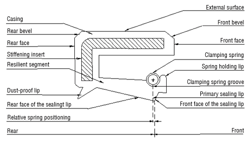
- an external cylindrical surface made from steel sheet metal or elastomer which seals the ring and makes it possible to properly encase it,
- a sealing elastomer lip /movable and resting shaft sealing/. An additional dustproof lip provides protection form dust and other solid impurities.
Due to their very wide application in many branches of industry, rings sealing rotation shafts have required well-developed standardisation with regard to the dimensions, materials, types. This study provides primarily information on this matter, which will enable the user to move in the maze of materials and catalogues of individual manufacturers.
Terminology, construction process
Terminology, construction process

Elements of standardisation - norms
- PN - 72/M-86964 - shaft sealing rubber rings with a metal stiffening insert - dimensions
- PN - 72/M-86965 - shaft sealing rings with in metal casing - dimensions
- PN - 88/M-73067 - rotation shaft sealing rings ISO compliant - nominal dimensions and tolerances
- PN - 81/M-86960 - rubber rings for sealing rotation shafts, ISO compliant - shared requirements and tests
- ISO 6194/1-1982 - rings for radial sealing of rotation shafts - nominal dimensions and tolerances
- ISO 6194/2-1991 - rings for radial sealing of rotation shafts - glossary
- ISO 6194/3-1988 - rings for radial sealing of rotation shafts - storage and installation
- ISO 6194/4-1988 - rings for radial sealing of rotation shafts - testing procedures
- ISO 6194/5-1990 - rings for radial sealing of rotation shafts - flaw identification
- DIN 3760 - rings for radial sealing of rotation shafts
- DIN 3761 - rings for radial sealing of shafts in cars, parts 1 to 15 - the norm includes all aspects with the glossary, requirements for the material and testing methods.
Structural variations
| structure | structure variation | marking according to ISO 6194/1 | marking according to DIN 3760 | marking according to ERIKS |
| Type: rubber with a metal stiffening insert | ||||
 | without a dustproof lip | type 1 | A | R |
 | with a dustproof lip | type 4 | AS | Rst |
 | springless | - | - | RZV |
| Type: in a metal casing | ||||
 | without a dustproof lip | type 2 | B | M |
 | reinforced without a dustproof lip | type 3 | C | GV |
 | with a dustproof lip | type 5 | BS | Mst |
 | reinforced with a dustproof lip | type 6 | CS | GVst |
 | springless | - | - | MZV |
Materials
| symbol | basic type | working temp. range | operating environment |
| NBR | -40°C +100°C | resistant to: engine, transmission and fuel oils, hydraulic fluids, grease, emulsions, oil-water emulsions and water, not resistant to: synthetic slow-burning liquids and brake fluids. | |
| ACM | -20°C +130°C | resistant to: engine and transmission oils, hydraulic fluids, not resistant to: water, oil-water emulsions, synthetic slow-burning liquids and brake fluids. | |
| MQ MVQ | -50°C +150°C | resistant to: engine and transmission oils, hydraulic fluids, oil-water emulsions. | |
| FPM FKM | -30°C +180°C | resistant to: engine and transmission oils, hydraulic fluids, fuel oils, oil-water emulsions, synthetic slow-burning liquids. |
Markings

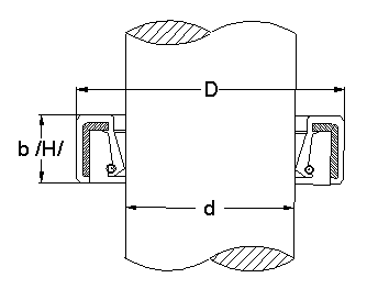
d - nominal shaft size [mm]
D - nominal socket size [mm]
b /H/ - width /height/ of the ring [mm]
Full marking of the ring:
d x D x b - structural type - class / material symbol
Example: a ring with a dustproof lip in a metal casing from the FPM material d=17mm D=33mm b=8mm
17 x 33 x 8 Mst FPM
Tolerances
- ring width tolerances in accordance with ISO 6194/1
- external diameter tolerances in accordance with DIN 3760
Diagnostics
| symptoms | cause | prevention |
| 1. Leakage |
|
|
|
| |
|
| |
|
| |
|
| |
|
| |
|
| |
|
| |
|
| |
| 2. Grooves, scratches or wear of the lip |
|
|
|
| |
|
| |
| 3. Excessive wear or hardening of the lip |
|
|
|
| |
|
| |
| 4. Shaft wear |
|
|
| 5. Scratches on the external diameter of the sealing |
|
|
|
| |
|
| |
| 6. Damaged sealing body |
|
|
|
| |
| 7. Damaged spring |
|
|
|
| |
| 8. Rolled up lip |
|
|
|
| |
|
|
The data present in this study are for information only. They may not be used as a basis for civil legal claims. Detailed questions should be directed to the Manufacturer. The Manufacturer reserves the right to introduce changes, according to new technical solutions and progress in the area of technologies and materials.

 Sealing systems
 Our Partners
